

Detalles de contacto:
+86 17852488518

Product Overview
The Hydraulic Metal Plate Rolling Machine is a high-efficiency forming unit specifically designed for rolling metal plates into cylindrical shapes. It is widely utilized in heavy industries such as pressure vessel manufacturing, pipeline engineering, steel structure construction, wind turbine production, shipbuilding, and bridge formwork fabrication. Based on the principle of continuous three-point rolling, the machine achieves high-precision plastic forming—transforming flat plates into arc or cylindrical workpieces—by precisely controlling the relative positions of the rollers to apply progressive pressure.
Compared to traditional, complex manufacturing workflows involving plate cutting, butt-welding, alignment, and lathe machining, this equipment enables single-pass rolling and forming. It offers significant savings in oxygen, acetylene, labor, and raw material costs, making it the ideal primary machine for producing circular components such as flanges, cylindrical shells, and air ducts.
Three Core Components
The equipment consists of three main parts: the main machine system, the hydraulic station system, and the electrical control cabinet system.
① Main Machine System
• Features a welded frame made of high-strength steel plate; post-welding annealing in a large furnace thoroughly eliminates welding stresses, ensuring high strength and stability during long-term operation.
• Both the upper and lower rollers are manufactured from high-quality 45# carbon steel, offering excellent wear resistance.
• Lower roller sliding bearings utilize SF-1 self-lubricating composite material, reducing maintenance frequency.
② Hydraulic Station System
• Equipped with an independent hydraulic system; an electric oil pump delivers high-pressure oil to the working cylinders or hydraulic motors via high-pressure lines.
• High-pressure oil drives plungers to generate thrust and torque, enabling profile bending through the tooling components.
• The hydraulic station features a water-cooling design, supporting sustained, continuous equipment operation.
• Hydraulic components are high-quality imports, ensuring a long service life.
③ Electrical Control Cabinet System
• Utilizes centralized push-button control with two operating modes: inching (manual) and linked (automatic).
• Pressure and stroke can be flexibly adjusted within specified ranges.
• Features a microcomputer control system for convenient parameter setting and adjustment.
Working Principle
Based on continuous three-point roll bending technology: metal material is fed between the upper and lower rollers, which are arranged at specific angles. By adjusting the vertical downward pressure of the upper roller and the angle of the side rollers, continuous, progressive compressive force is applied to the material. Under the combined action of compression and friction from the rollers, the metal undergoes plastic deformation, ultimately forming the desired arc-shaped or cylindrical workpiece.
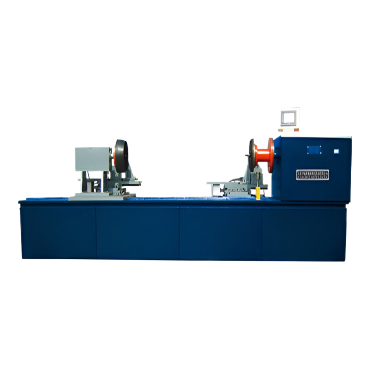
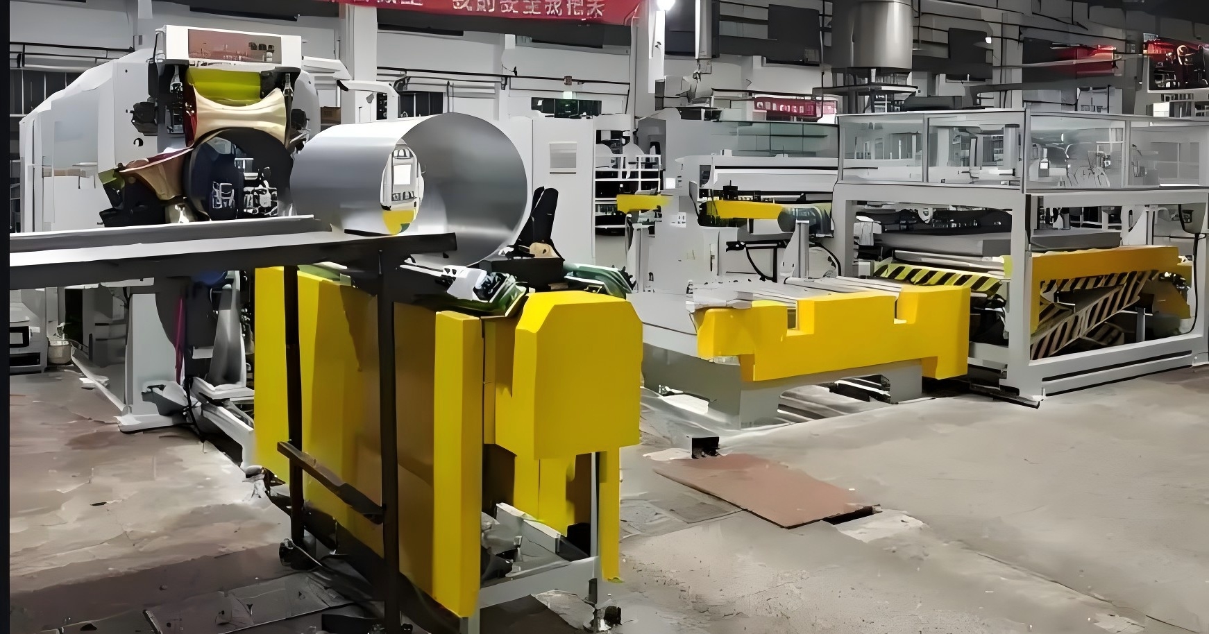
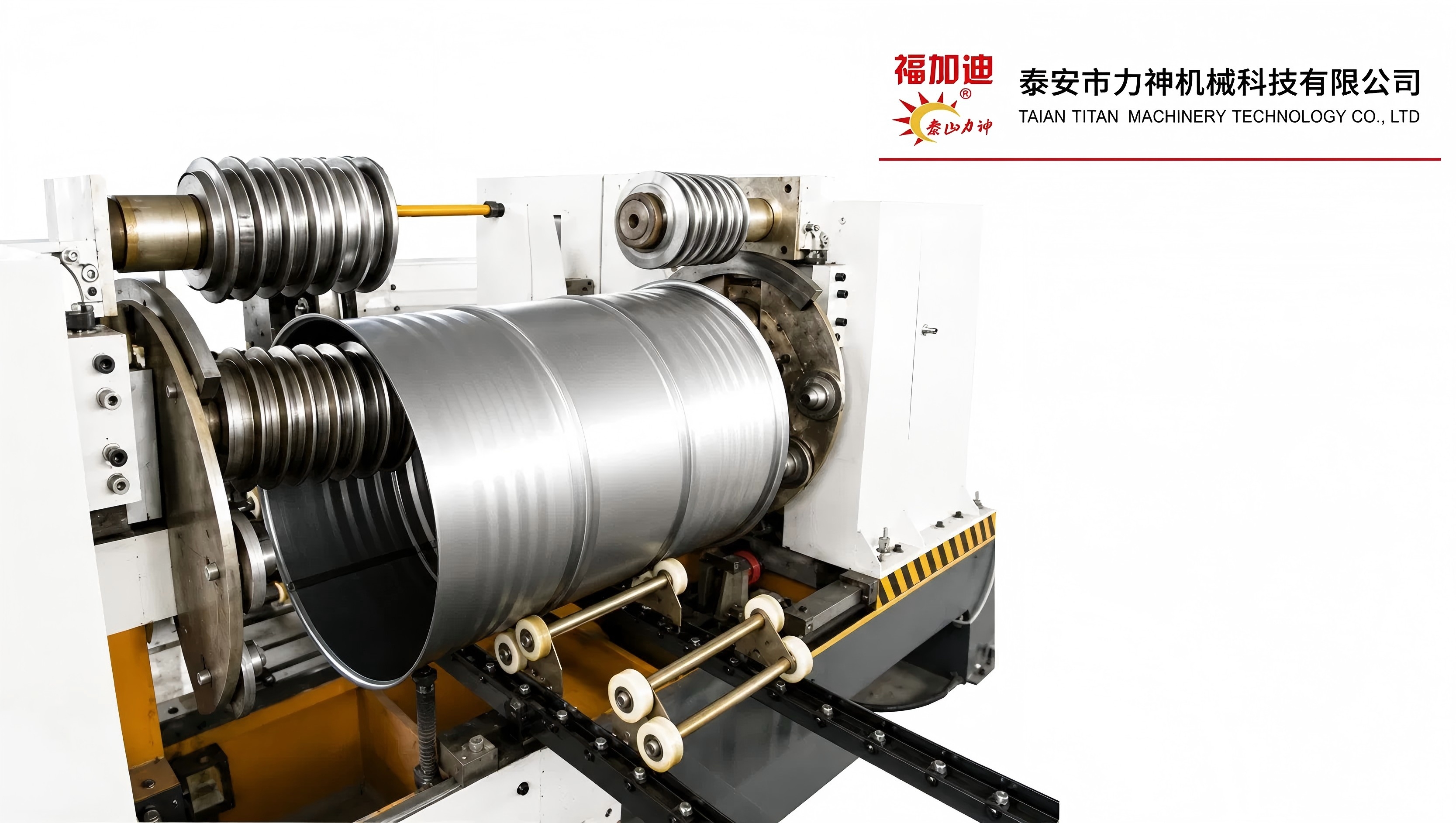
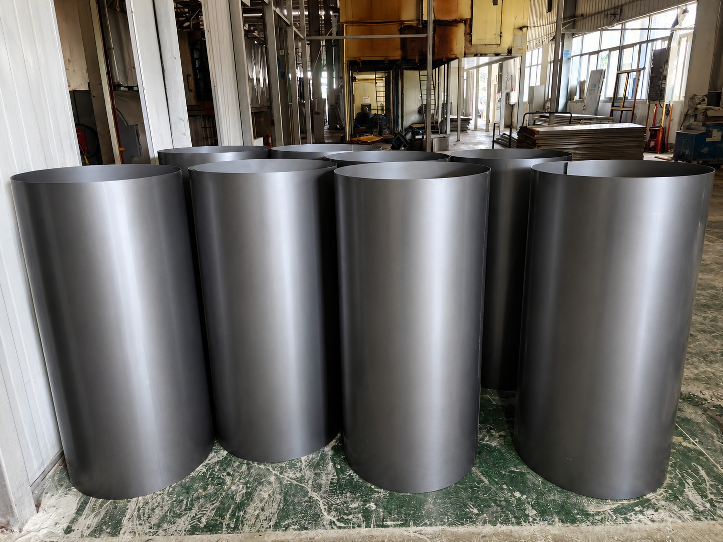
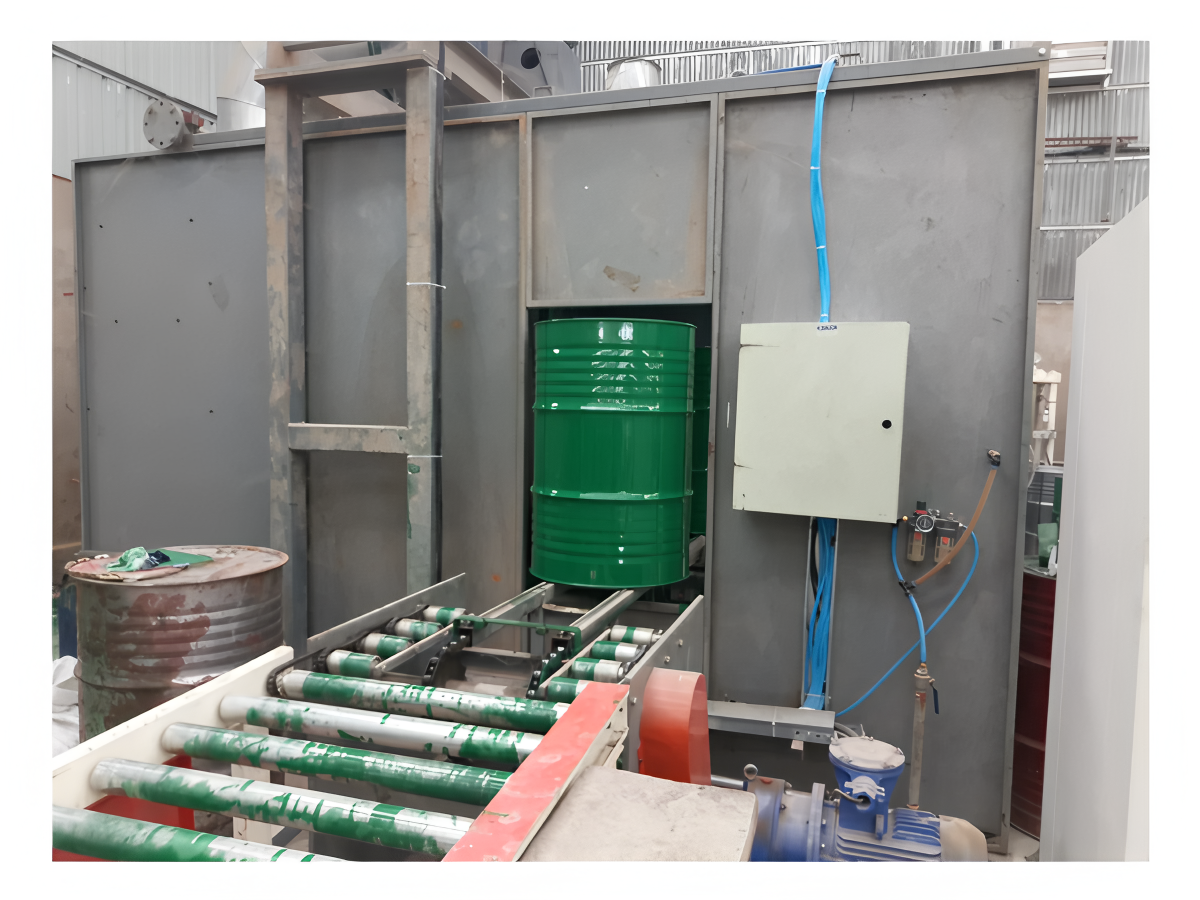
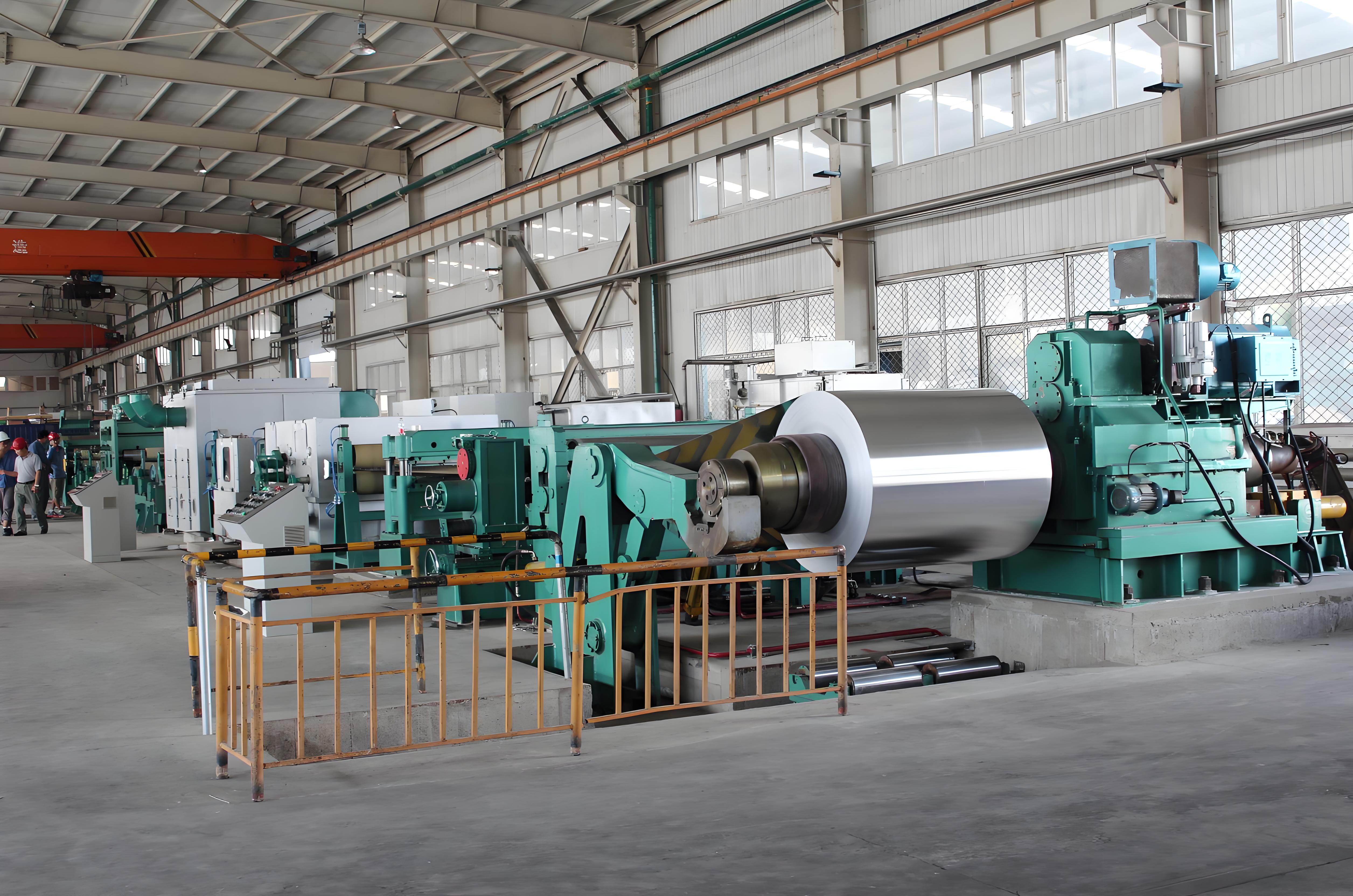
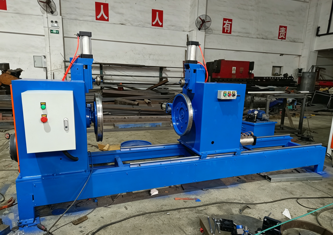
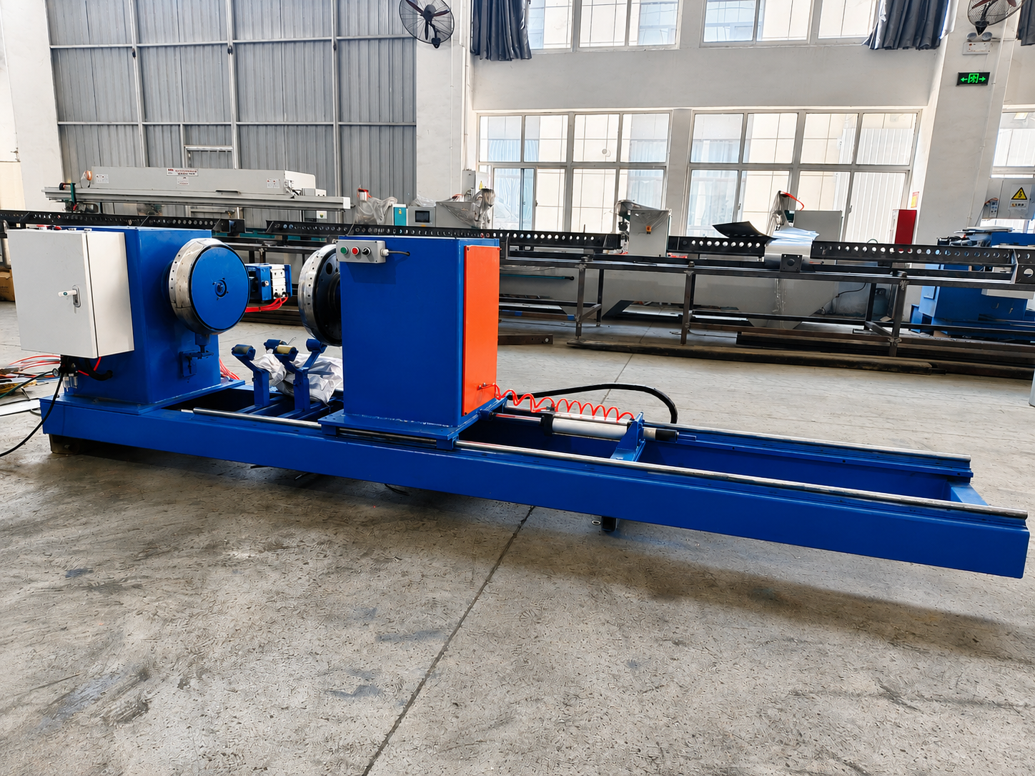

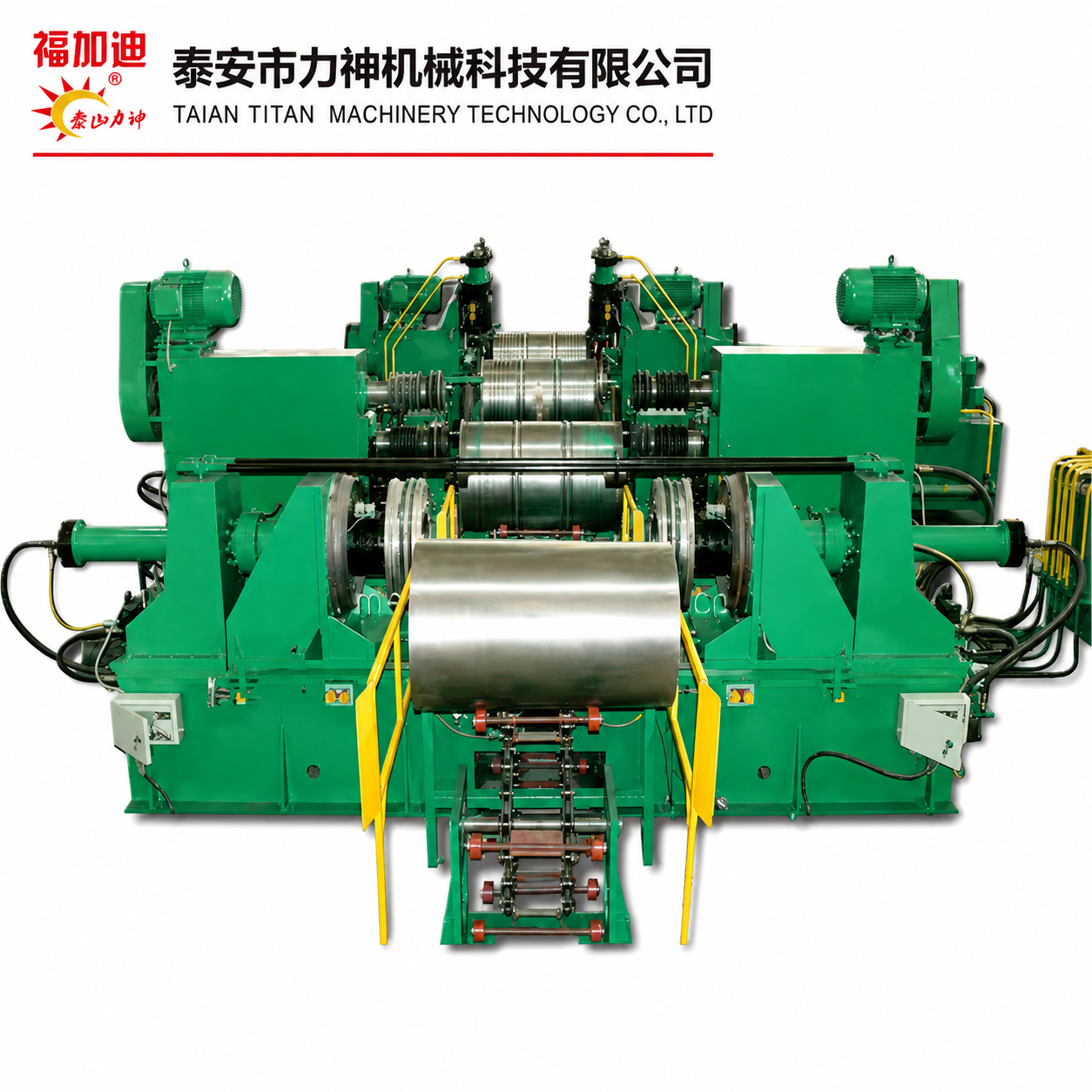

Plate Rolling Machine
A plate rolling machine is specialized equipment designed to bend flat metal stock into arcs or cylinders through a rolling process. It is widely used in sectors such as pipeline and air duct manufacturing, pressure vessel and storage tank fabrication, steel structure construction, and shipbuilding. Its core operating principle relies on continuous three-point roll bending: metal sheets are fed between rollers arranged at specific angles; by adjusting the relative positions and rotation of the rollers, continuous, progressive pressure is applied to the sheet, inducing plastic deformation to form the desired arc or cylindrical workpiece.
Basic Structure
The machine primarily consists of three main systems: the main machine unit, the hydraulic station, and the electrical control cabinet. The main unit comprises the frame, top roller, bottom rollers, transmission system, adjustment mechanisms, and support brackets. The top roller is typically the drive roller; it moves vertically to adjust downward pressure and provides the primary forming force. Two bottom rollers are usually arranged symmetrically on either side of the top roller, providing support while driving the sheet forward. Support brackets are used for long workpieces to prevent sagging or deformation during the rolling process. The rollers are generally manufactured from high-quality 45# carbon steel, and the bottom rollers often utilize SF-1 self-lubricating composite material for sliding bearings to reduce maintenance requirements.
Classification
Classification by roller quantity and layout:
Symmetrical three-roller plate rolling machine: The most common configuration. The top roller moves vertically between two symmetrically positioned bottom rollers, which act as the drive rollers. While simple in structure and cost-effective, this type leaves unrolled flat sections at both ends of the sheet (known as "residual straight edges"), necessitating pre-bending.
Asymmetrical three-roller plate rolling machine: The top roller position is fixed or only slightly adjustable, while one bottom roller moves vertically. This allows for pre-bending at one end of the sheet, thereby reducing the residual straight edge.
Four-roller plate rolling machine: Features a four-roller layout where side rollers can be actively tilted and adjusted. This enables pre-bending at both ends of the sheet, completely eliminating residual straight edges. The entire cylinder can be rolled in a single setup, though the machine is structurally complex and more expensive. Classification by Drive Mechanism:
Mechanical plate rolling machines: These rely on mechanical transmissions—such as gears and worm gears—for operation and adjustment. They feature a robust, durable structure and are suitable for rolling thin plates and small workpieces.
Hydraulic plate rolling machines: These utilize hydraulic systems to drive the lifting and downward pressing of the rollers. They offer greater force, smooth and precise adjustment, and a high degree of automation. Capable of handling heavy-duty tasks—such as rolling thick plates—that are difficult for mechanical machines, they are currently the mainstream equipment in the plate processing industry.
Application Areas
Plate rolling machines serve a wide range of industrial sectors within the national economy. In pressure vessel and boiler manufacturing, they are used to roll cylindrical shells. In the fields of steel structures and bridge formwork, they produce curved components; specialized machines utilizing a four-roller adjustable system can significantly shorten the production cycle for double-curvature formwork. In shipbuilding and heavy machinery, they shape curved hull plates. In fan and ventilation engineering, they facilitate the mass production of fan housings and duct flanges. Additionally, they are applied in industries such as chemical equipment, wind turbine towers, oil pipelines, and metallurgical equipment. Beyond flat plates, specialized rolling machines can also bend profiles such as angle steel, channel steel, and round pipes into curved shapes.
Development Trends
The evolution of plate rolling machines has progressed from mechanical and hydraulic types to CNC-controlled models. Current industry trends show large-scale equipment advancing toward the processing of thick, ultra-thick, high-strength, and composite plates to meet the demands of sectors like chemicals, boilers, and pressure vessels. Meanwhile, small-scale equipment is evolving toward capabilities for thin-gauge materials, extra-long workpieces, complex curvatures, and CNC integration. The proportion of equipment equipped with PLC control modules continues to rise, and the levels of digitalization and automation have become key benchmarks for assessing equipment sophistication.


Este sitio web utiliza cookies para garantizar que obtenga la mejor experiencia en nuestro sitio web.


 English
 Pусский
 Français
 العربية


 Teléfono